views
Plugging in and Setting the Ammeter
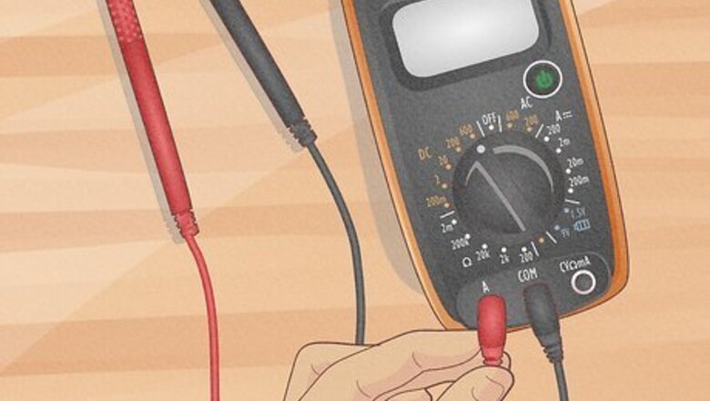
Insert the black lead into the COM port on the ammeter. Every ammeter comes with red and black wires that connect the device to an electrical circuit. The probe end of each wire is what connects to the circuit. The opposite end plugs into a slot on the multimeter, which is always the COM port for the black wire. Many multimeters have the ability to test amperes (A) and can be used as an ammeter. Even if you’re using a multimeter, the black lead always connects to the COM port. Make sure you’re using the correct ports! Improper wiring could cause the ammeter to burn out later.
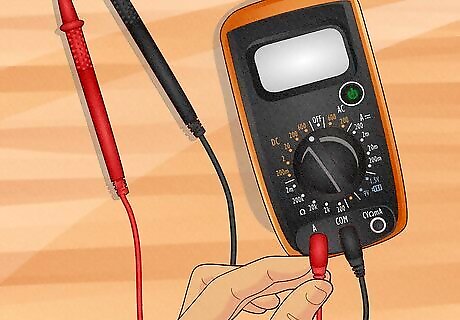
Connect the red lead to the A port on the ammeter. Note the ports carefully since some devices may have multiple ones. The ampere port, labeled with an A, is the correct one for testing a current’s strength. Ignore the mΩ port if your meter also has it. Fit the red lead in place to finish wiring the ammeter. If you’re using a multimeter, you may only see a port labeled VΩmA or something similar. Fit the red lead into that port. It works with all of the multimeter’s functions. If your device has a separate port like VΩ, it is used to test voltage and resistance
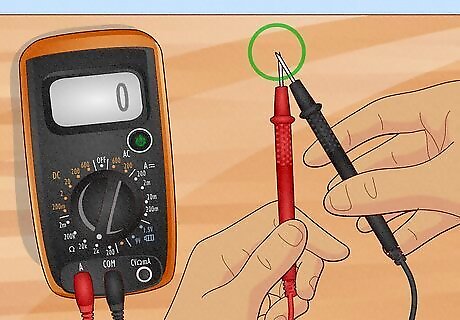
Touch the metal probe tips together to test the ammeter. If you’re using a multimeter with an ammeter setting, switch the dial to resistance. Resistance is indicated by the omega symbol, or Ω. When you touch the probes together, look for the meter to display 0. It means that electricity is able to flow through the meter without trouble and you will get a clear result when you use it for testing purposes. If the display stays at 1, the meter could be broken. It happens sometimes when the fuse burns out from a strong electrical shock. If your meter doesn’t have a resistance setting, you won’t be able to test it this way. Try wiring it into a circuit. If it doesn’t react when the power is on, then it is probably burnt out.
Set the meter dial to AC or DC depending on the current you are testing. Many modern ammeters and multimeters have both AC and DC settings. Use the dial in the center of the meter to choose one. In a direct current (DC) circuit, the electricity moves in a single direction. In an alternating current (AC) circuit, the current can change directions. An example of a DC current is a battery circuit. The electricity flows from the positive terminal, around the circuit, and back to the negative terminal. AC circuits are used to route power in homes, office buildings, and other areas that require high amounts of electricity. Note that some ammeters only test AC or DC. If yours is like this, it will most likely be labeled and you won’t see different settings to choose from. AC is often represented by a squiggly line, while DC is represented by a straight line.
Set the range scale on the ammeter to match the circuit you are testing. Turn the central dial to adjust the meter’s range. Start with the highest setting available, which is often 2 A. As you use the ammeter to test the circuit, gradually turn the meter down until you get a consistent, accurate reading. The ammeter’s display will change accordingly. Many ammeters have different settings from amps to milliamps and microamps. For comparison, an amp is 1,000 milliamps. A basic circuit with a small battery can be measured in milliamps. You could set the meter at 2 A, then turn it down to a milliamp setting until you get a consistent readout. More powerful circuits, such as the ones in your home, are better measured in amps. Many ammeters automatically calculate the range. If your meter doesn’t have range settings, then you don’t have to worry about setting it yourself.
Wiring the Ammeter into a Circuit
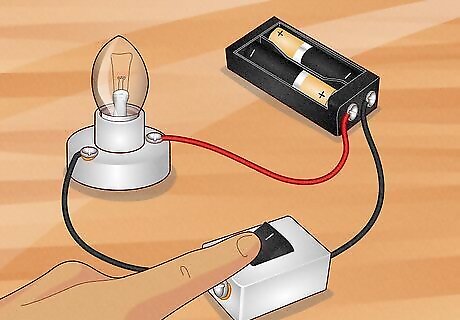
Turn the power off before attempting to handle a circuit. Using an ammeter requires you to mess with electrical components. If you’re testing a circuit containing a battery, make sure the power switch is off before you disconnect the battery. If you’re testing a bigger circuit, toggle any controlling electrical switches before deactivating the electricity completely. For example, if you’re testing a home circuit, shut off power at the circuit breaker or fuse box. The box is usually hidden in an out of the way spot, such as in the basement or garage.
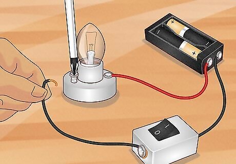
Unplug a wire to break the circuit and make room for the ammeter. Unlike other devices, an ammeter has to be incorporated into the circuit. Find a spot where you can disconnect wires or other components. Create plenty of room to fit the ammeter and its probes between the components. For example, if you’re using a battery to light up a small bulb, you might detach a wire from the bulb. You could then fit the ammeter between the wire and bulb. If you try to touch the probes to a complete circuit, you will most likely short-circuit the ammeter. Ammeters have little resistance, so the electricity has to pass through it in a very specific way to prevent it from burning out.
Connect the black probe to the negative end of the circuit. The leads are color-coded so you know exactly where each one fits in the circuit. The black probe is meant to direct electricity away from the ammeter. Many ammeters include clamps you can place on the ends of circuit wires to keep the probes pinned to them. Make sure the tip of the probe touches the exposed end of the wire. For example, you could connect the black probe to a wire leading toward the negative terminal on a battery powering the circuit. You could also touch it directly to the battery terminal. For home circuits, connect the probe to the exposed end of a black wire leading toward your home’s electrical supply.
Join the red probe to the opposite end of the circuit. The red probe connects to a wire or device the same way as the black probe. It may be connected to a red power wire leading to a device like a lightbulb or to the device itself. With both the red and black probes connected, the circuit will be complete, allowing electricity to flow through the ammeter. For instance, if you have the ammeter between a battery and a lightbulb, the red probe may connect to the lightbulb. The black wire can touch the battery’s negative terminal or a wire connected to it. If you’re working with a battery, don’t connect both probes directly to the battery’s terminals. It may cause the ammeter to burn out. Keep in mind that the wire coloring scheme can differ from place to place. However, black usually indicates a negative current and red indicates positive one.
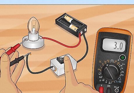
Turn the power back on to measure the current strength. Make sure your ammeter is on and wired correctly. Once you’re ready, activate the circuit as well as your home’s circuit breaker or fuse if you turned it off. You will see the ammeter’s screen display change as the current runs through it. When you’re done, turn off the power again before putting the circuit back together.
Using a Clamp-on Ammeter
Press the button on the clamp to open it. The clamp is often built into the top of the ammeter. You will see a big, red button you can press to open the clamp. Some digital ammeters also have a plug-in clamp accessory that works similarly. If yours is like this, plug the clamp into the ammeter’s open ports first before opening the jaws. If you have a plug-in clamp, it will be color-coded like the regular probe leads ordinarily used to test amperage. Plug the black lead into the COM port and the red lead into the A or VΩmA port. Clamp-on ammeters are a more advanced kind of device that can read electrical currents without you ever having to take apart a circuit. It is even easier to use than the older digital models.
Fit the jaws around a single wire you wish to test. Whatever you wish to test should be inside the jaws. If you try to test more than 1 thing at a time, the ammeter may not detect any current. This is especially important if you’re trying to test something like an extension cord consisting of multiple wires. Separate the individual wires if you can and then test them all separately. The main wires to test include the black and red or white ones. These wires are the ones that often conduct the full electrical current in a circuit. This coloring scheme can vary depending on where you live, however. The great thing about clamp-on ammeters is that you don’t have to detach the conducting wires at all. As long as the wires are well-insulated, you don’t even have to turn off the electricity. However, remember to avoid touching exposed wires or other metal components that could shock you.
Adjust the control dial to test amperage at the proper range. The exact options available will vary depending on the meter you have. Most clamp-on models have a single setting for amperage and detect the range automatically. Set the dial to A, often marked with a squiggly line to represent alternating (AC) current. Most clamp-on ammeters detect both AC and DC current, so you can use the same dial setting. Some ammeters have a few range settings. Make sure you’re using the correct one. Generally, start with the largest setting and turn the dial down if you expect a weaker current. Keep in mind that clamp-on ammeters are usually multimeters that also test resistance and other measurements. Make sure you’re using the correct settings for ammeter mode.
Take the reading before detaching the ammeter. Activate the electrical current if it isn’t already on. Watch for the ammeter’s screen to light up and display the strength of the current in amps. When you’re done, press the trigger on the ammeter’s jaws to remove them and slide them off the wire you tested. The ammeter works by detecting the electrical field around the wire. It is just as accurate as one you have to wire into the circuit. Keep in mind that wires of a different color can give you different readouts. The black and red power wires, as well as white neutral wires, will show you the true power of the circuit. Other colors, such as green ground wires, don’t conduct the full current.


Comments
0 comment