views
Building the Wheels
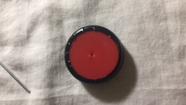
Poke a tiny hole through the plastic bottle cap, small enough for the rod to fit in.
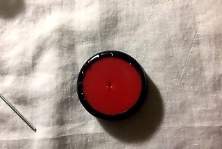
Wrap the bottle cap edges with tape. Electrical tape is useful here since it provides a rubbery grip around the wheel. Wheel1.jpg
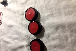
Repeat the process 3 more times to the get 3 more wheels. IMG_4889.jpg
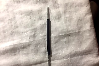
Take a straw and cut the ends so it’s shorter than 4 inches to cover the rod. Insert the 4-inch rod into both wheels and make sure the rod is exposed at both ends.Wheel4.jpg
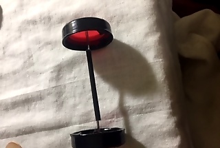
Glue the rod to the wheels. Let it dry.IMG_4893.jpg
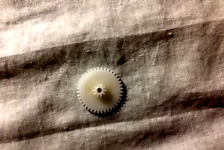
Insert a tiny gear to one side of the other exposed rod. Glue the other 2 wheels to the rod, and let it dry. This will allow the motor to turn the rods thus spinning the wheels. IMG_4898.jpg Wheel6.jpg
Constructing the Body
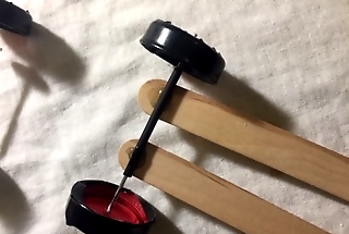
Place 2 popsicle sticks next to each other. Glue both rods to the sticks. IMG_4902.jpg
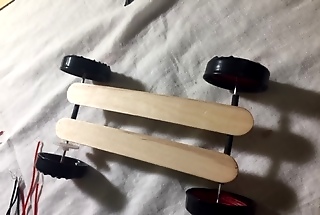
Wait for the glue to dry.IMG_4903.jpg
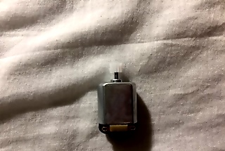
Insert the tiny gear into the shaft of the DC motor. 2body6.jpg The shaft is the thin rod of the motor.
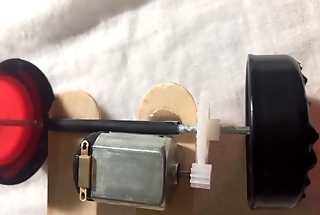
Flip the car upside down so the rods are facing up. Align the gear of the motor to the gear of the rod perfectly so when one gear moves the other gear will move as well. Glue the motor and wait for it to dry. IMG_4907.jpg
Wiring the Car
Familiarize yourself with the equipment. These steps will require you to have basic knowledge on how to solder. If you don't know, check out How to Solder Wires Together.
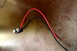
Take a 9V battery clip buckle. Notice that there are two wires attached red (+) and black (-). These wires are tied to the DC motor that is supplying power.IMG_4982.jpg
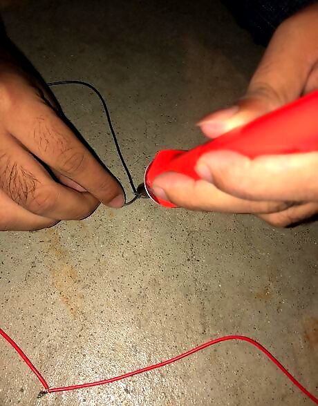
Take two ends of the same wire either red or black and try to tie a small knot. Then place a hot soldering iron and melt the solder wire over the knot to permanently connect the two wires.
Repeat this process as needed to extend the wire length. Remember that you should connect red wires to red wires and black wires to black wires.
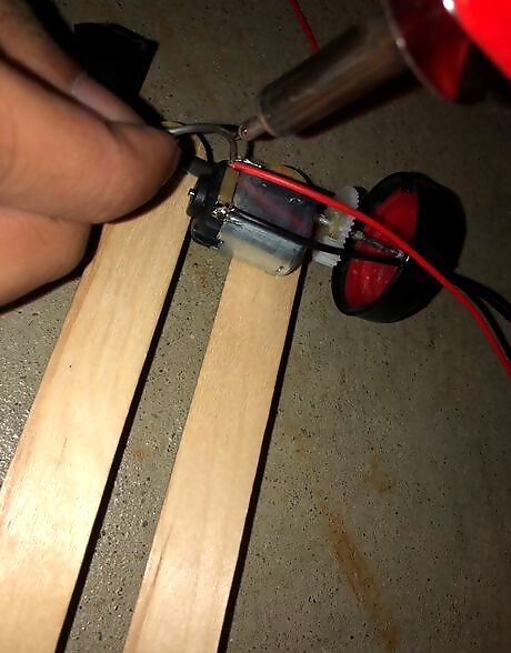
Connect both of the wires to the motor. Take the end of the red wire and solder it to the top hole of the motor (positive eyebolt). Repeat this process for the black wire, soldering it to the bottom hole (negative eyebolt).
Test it. Snap the clip buckle at the end of the wires to the 9V battery. If everything is done correctly, the shaft will spin clockwise making the car move forward. Note: On the clip buckle, the smaller terminal is positive and the larger terminal is negative. When attaching the larger negative terminal of the clip buckle to the smaller positive terminal of the 9V battery and vice versa, the shaft spins clockwise, causing the car to move forward. Likewise, when placing the larger negative terminal of the clip buckle close to the larger negative terminal of the 9V battery, the shaft spins counter clockwise, causing the car to move backward.
Controlling the Car
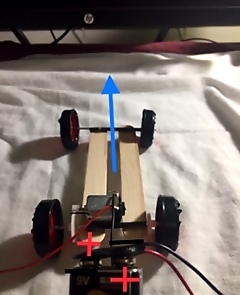
Drive it forward. Attach the larger negative terminal of the clip buckle to the smaller positive terminal of the 9V battery and vice versa. This will enable the car to move forward.
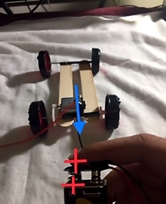
Drive it backward. Place the larger negative terminals and smaller positive terminals of the clip buckle and the 9V battery on top of each other. This will enable the car to move backward.








Comments
0 comment