views
- Be sure to note how old your ATX PSU is. Older PSUs utilize the 3.3V and 5V rails. Newer versions use the 12V rail.
- Bundle your wires and label them by color.
- Test the box with an ohm-meter before applying power.
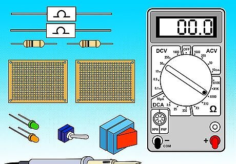
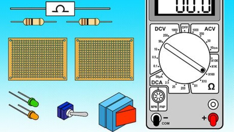
Ready your materials (See "Things you'll need" below)
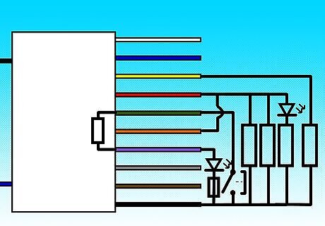
Plan the design of your new PSU. Create a circuit map to follow so to avoid confusion. Remember that there will be a difference between older and newer ATX PSUs. Older PSUs will mainly utilize the 3.3V and 5V rails, with excess current being handled by the 12V rail. Newer versions will use the 12V rail as their main output.Use an Old ATX Power Supply As a Lab Power Supply Without Modification Step 2Bullet1.jpg
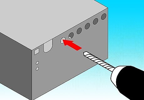
Drill the holes you need to mount your binding posts, LEDs, and main switch.

Cut your wires and group them by color. The color guide is as follows: Black: GroundUse an Old ATX Power Supply As a Lab Power Supply Without Modification Step 4Bullet1.jpg Orange: +3.3VUse an Old ATX Power Supply As a Lab Power Supply Without Modification Step 4Bullet2.jpg Red: +5VUse an Old ATX Power Supply As a Lab Power Supply Without Modification Step 4Bullet3.jpg Yellow: +12VUse an Old ATX Power Supply As a Lab Power Supply Without Modification Step 4Bullet4.jpg Blue: -12VUse an Old ATX Power Supply As a Lab Power Supply Without Modification Step 4Bullet5.jpg Green: Power OnUse an Old ATX Power Supply As a Lab Power Supply Without Modification Step 4Bullet6.jpg Purple: +5V StandbyUse an Old ATX Power Supply As a Lab Power Supply Without Modification Step 4Bullet7.jpg Gray: Power GoodUse an Old ATX Power Supply As a Lab Power Supply Without Modification Step 4Bullet8.jpg Brown: +3.3V SenseUse an Old ATX Power Supply As a Lab Power Supply Without Modification Step 4Bullet9.jpg White: -5V (Old PSUs only)Use an Old ATX Power Supply As a Lab Power Supply Without Modification Step 4Bullet10.jpg
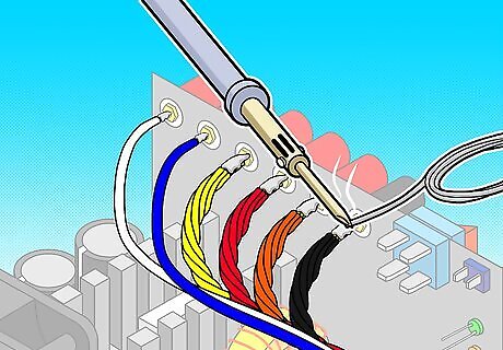
Solder the wire bundles (Excluding the mains) to their respective binding posts. (Remember to label these so you which is which.
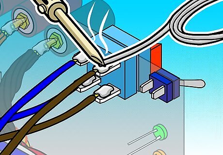
Solder the main wires to the switch.
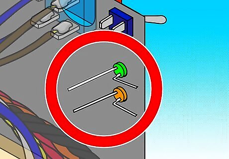
Begin connecting LEDs to your load switch Connect the load switch between 'Ground' and 'Power On'.Use an Old ATX Power Supply As a Lab Power Supply Without Modification Step 7Bullet1.jpg Use a current limiting resistor as you connect the green LED between 'Ground' and one of the positive outputs of the power supply (i.e. +12V for the newer models, +5V for older)Use an Old ATX Power Supply As a Lab Power Supply Without Modification Step 7Bullet2.jpg Use a current limiting resistor as you connect the red LED between 'Ground' and '+5V Standby'Use an Old ATX Power Supply As a Lab Power Supply Without Modification Step 7Bullet3.jpg
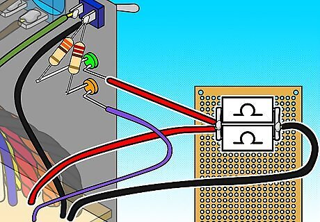
Attach your 10-Ohm/10-Watt resistors to a piece of prototyping board and bend the leads to avoid movement. Isolate these resistors then connect them to your ground and positive output wires.
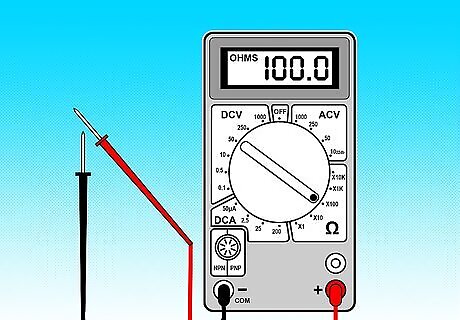
Test the box with an ohm-meter before applying power. Make sure there are no unexpected connections, and that the proper connections are made.
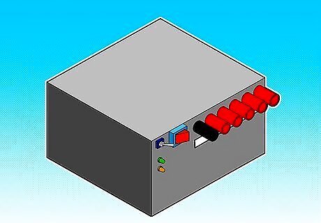
Here's a picture of the finished box:


Comments
0 comment